|
|||||||||||||||||||||||||||||||||||||||||||
|
|
|||||||||||||||||||||||||||||||||||||||||||
|
Introduction |
|||||||||||||||||||||||||||||||||||||||||||
|
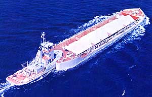
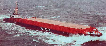
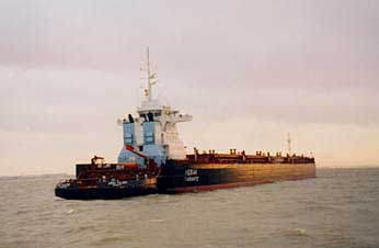
"Big Load Afloat" issued 1965 by The American Waterways Operators, Inc. tells that the method of operating non-powered barges under pushing from astern by a powered boat was born as a reformation of "alongside-towing" in the river Mississippi or one of its tributaries seemingly something more than hundred years go, but the question "Who is the inventor ?" cannot find answer even now. But, the man who tried this method first in the world should be profoundly admired, because, in the past hundred years, it has grown up to a standard system of mass-transport in inland traffic not only in the United States but also in other continental countries. In Japan consisting of four mountainous islands without navigable inland waterway, the introduction of push-barge method took place for the first time in 1963 for the transport of sand for building an artificial island in Kobe Harbour, and its high economical efficiency was so rapidly and widely acknowledged that the push-barge train has soon become the standard method of reclamation. Then, it was not so long before the shipping companies began to introduce this system for transporting limestone, coal, aggregates, etc., but such a rapid expansion was within an absolute limitation, because rope-connected trains had to be use in wavy sea from the first day of introduction and, in spite of great efforts and costs paid for improving navigability, the fields of their activity were limited within the western inland sea and larger bays. Under these circumstances, we decided to work out a solution to the problem of navigability through developing mechanical coupler systems of articulate connection type, and, considering the characters of existing demands peculiar to Japan, we were obliged to follow two different ways --- one with the highest seaworthiness to cover ocean-going or unrestricted services and another with some limited navigability covering the sea states permitting reclamation work but capable of slipping, when so needed, to permit dumping of load of dump-barges without disconnection --- and decided to develop the latter type, slippable coupler, earlier because a greater number of demands could be expected. Before this stage, we had already had some experiences in treating rope-connection and articulate coupler of peculiar design, and, based on these experiences, it was intended to develop couplers having the following basic characteristics:
|
|||||||||||||||||||||||||||||||||||||||||||
|
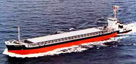
Articouple F (1972, ref. page "Articouple F") |
|||||||||||||||||||||||||||||||||||||||||||
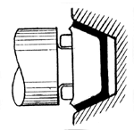
It was intended to develop a system which can keep navigability up to a wave height of 3 - 3.5 metres -- about twice the height permitting reclamation work -- and, in addition, permits slipping, when loosened, without perfect separation from the barge. It was believed that the only applicable functional momentum would be "friction" for which we already had experience of application. After several tentative designs, the following design principle was adopted :
|
|||||||||||||||||||||||||||||||||||||||||||
|
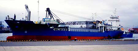
Articouple H (1975) |
|||||||||||||||||||||||||||||||||||||||||||
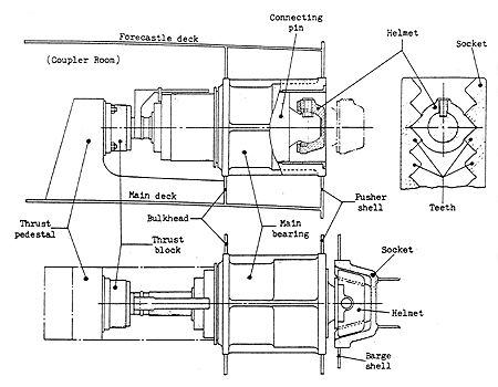
Along with the rise of reputation of Articouple-F, a demand has risen for a system with improved sea-worthiness covering ocean service and, in reply to such a demand, a new system was intended. The new system was not required to cope with change of draught relationship during navigation, while it had to assure the unrestricted service, and it was decided to develop a system, named Articouple H, of multi-step tooth-engagement type based on the following design principle :
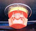
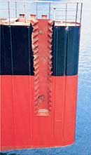
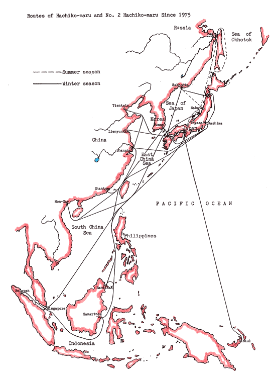
Experiences with Articouple-H couplers of these Japanese and Russian fleets were enough for us to confirm the conviction on the competence and reliability of our coupler technology in general as well as in details of design. Although Articouple-H type was replaced with K type afterwards as stated below, many important items of its design philosophy and details are inherited by various successors. In the stage of development of Articouple-H, there were two observations --- whether the teeth should be provided on both oblique walls of socket or they should be on one (rearward) oblique wall only and the other wall should be a vertical flat wall. But, on the other hand, we were convinced that finer steps, or smaller intervals between teeth would result in easier connection work and the teeth provided on one side only needing wider intervals to maintain necessary strength of teeth would be more inconvenient in handling. In this connection, it was also studied to provide teeth in plurality on both sides of helmet, for example 3 by 3 forward and rearward sides, to make the intervals between connecting positions smaller. But this proposal was not adopted because uneven time-wear of teeth of sockets was considered inevitable after use for a long time --- 15 to 20 years --- and, as the results, uneven distribution of load due to uneven contact --- total load on two teeth or even on one tooth only --- was anticipated. So, the type "one tooth on each side" combined with socket with double-row teeth was adopted. But our above-mentioned fixed idea was turned over by the experience of the captain of the first Articouple-H pusher "Hachiko-maru". He was an excellent captain having served as captain of the first Articouple-F pusher "Akashi-maru" and had the largest experience in dealing with Articouple-pushers. As a recommendation based on his own experience of actual use, he said wider intervals between teeth would make connection easier. In addition, different from Articouple-F, Articouple-H had a drawback that longitudinal (fore-and-aft) pre-positioning of pusher was needed before connection and, for this purpose, the pusher had a "Positioner" independent of the main coupler. So, the conclusion was self-evident. Manufacture of Articouple-H couplers was interrupted up to the 6th set --- 2 Japanese and 4 Russian. The rhombus-like double-toothed helmet was changed to pentagonal single-toothed one, the double-row teeth sockets changed to single-row teeth and the positioner removed, and all other design philosophy and experiences were transferred to the next improved type Articouple K. Even the manufacturing cost was doubtlessly reduced.
|
|||||||||||||||||||||||||||||||||||||||||||
|
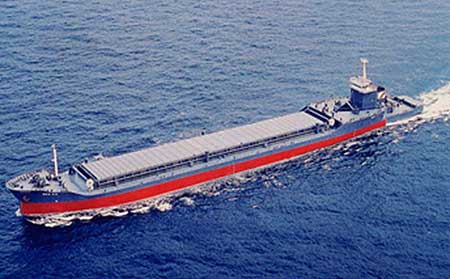
Articouple K (1980, ref. page "Articouple K") |
|||||||||||||||||||||||||||||||||||||||||||
|
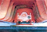
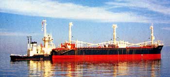
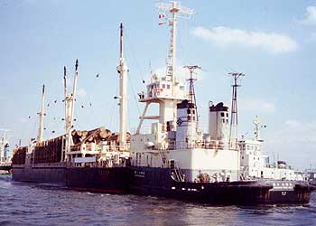
Articouple K was born as an improvement of Articouple H. The cross-section of the helmet and socket were changed into asymmetric trapezoid with the rearward side with teeth parallel to Y-axis for easier manufacture. The oblique forward side is utilized for longitudinal (fore-and-aft) positioning which will take place in the course of connection. This manner of shaping has an effect to improve stable motion of helmet during connection and disconnection and connection under some influence of waves has become possible to a certain degree. All other merits of Articouple H were inherited by Articouple K. The first two units of Articouple K were exported to Scandinavia. Then, several demands from domestic owners followed and, in parallel, demands from Scandinavia were repeated up to 14 units in total. 10 of them are of a same type of deck-mountable design and arranged to be swappable with one another so that cooperation over borders may be possible. Some of these boats were converted from existing tugs through addition of deck-mountable couplers. In addition to the superexcellent reliability, one of the merits of Articouple K is, practically speaking, the absence of wearing parts needing periodical renewal. Articouple and Triofix couplers are designed for hydraulic drive by means of hydraulic cylinders. But there are two exceptions designed for rotary hydraulic motor powered threaded shaft drive, named KM. These two units, with ABS classification approval, were exported to Argentine in 1981 to form 180 m long trains with articulation at mid-length, each consisting of two 90 metres long oil barges, powered and dumb.
|
|||||||||||||||||||||||||||||||||||||||||||
|
Articouple FR (1984, ref. page "Articouple FR") |
|||||||||||||||||||||||||||||||||||||||||||
|
In reply to various owners' demand for a system permitting dumping of load of a dump-barge without separation and, at the same time, assuring a good seaworthiness, a coupler of combined friction- and tooth-engagement principle was developed as Articouple FR. The first FR-pusher was converted from a rope-connected pusher and was used to operate a tank barge for offshore dumping of industrial wastes in the area more than 50 nautical miles from shore. The second one was a sand barge which was converted afterwards to a dredge barge with a sand pump. The performance of Articouple FR in "Draught adjustment" was sufficient to cope with the rapid change of draught due to loading by the sand pump in waves 3 - 4 metres high. Then, a number of dredge barges with FR-couplers were built, and, in addition, Fr-couplers were employed even on a number of ordinary cargo barges because of its convenience in use --- cargo-handling utilizing "Draught adjustment" without separation of pusher. In addition, the presence of friction component assists to easier connection under the influence of waves because friction-connection can serve as the provisional connection before proceeding to the final combined friction/tooth-engagement connection. .
|
|||||||||||||||||||||||||||||||||||||||||||
|
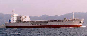
Triofix TRF (1989, ref. page "Triofix TRF") |
|||||||||||||||||||||||||||||||||||||||||||
|
The development of various types of Articouple has improved convenience in use remarkably, but, nevertheless, the matter of the owners' greatest concern --- Speed ---remained unsolved. In articulate connection permitting free relative pitching, a wide clearance must be left in front of the pusher's bow to prevent hitting of pusher's stem against the barge's stern notch wall, and eddies occurring in the open bottom of this clearance cause large water resistance. This is the very reason of the inevitable low speed of push-barge trains and, for realizing a drastic improvement of propulsive performance through suppressing generation of eddies, the rigid connection needing no clearance for permitting relative pitching is the only measure. In reply to an owner's request for a high-speed limestone barge of 10,000 DWT for long distance run, with draught-adjustable coupler, a new 3-pin supported rigid connection coupler Triofix TRF was developed. Though the side coupler unit of Triofix TRF may seem to resemble Articouple FR in external appearance their constructional principles are different from each other because of the characters of load components are different. The results of the first Triofix TRF were satisfactory --- comfortableness to crew on board because of absence of relative pitching and easy connection under influence of waves. After this first 10,000 tonner, a number of dredge barges connected with Triofix TRF were built. In the case of ordinary cargo barges or tankers, the bow unit may be a simple wedge-shaped coupler. In dredge barges which followed in plurality, however, rapid adjustment of draught is required due to rapid loading with a sand pump in 3 - 4 metres high waves, and the bow unit should preferably be of combined friction/tooth engagement similar to the side unit. This type is called Triofix TRF-F.
|
|||||||||||||||||||||||||||||||||||||||||||
|
Triofix TR (1990, ref. page "Triofix TR") |
|||||||||||||||||||||||||||||||||||||||||||
A number of non-powered floating cranes are operated with Articouple-pushers in Japan because of their easy manoeuvring and positioning. In compliance with an owner's desire to fix the pusher at the end of the pontoon of floating crane so that the total effective length of the combination, moving as a single floating body, may be increased for the purpose of reducing trim when lifting load, a new 3-pin supported rigid connection coupler of an extremely simple construction was developed as Triofix TR. The results were satisfactory. Afterwards, several cargo barges were built to be operated by pushers with Triofix TR.
|
|||||||||||||||||||||||||||||||||||||||||||
|
Triofix TK (2000, ref. page "Triofix TK") |
|||||||||||||||||||||||||||||||||||||||||||
Although the policy to apply Triofix TK, using Articouple K as side coupler units, to larger cargo and tanker barges had been settled long before, such a chance has not come. Triofix TK was applied to 30,000 tonners' fleet of Italian ILVA for the transport of steel coils from Taranto steel mill to Genova along Italian coast and the performance was just as anticipated. Triofix TK is most appropriate for larger cargo and tank barges to be operated in long distance services with high speed.
|
|||||||||||||||||||||||||||||||||||||||||||
|
Finally |
|||||||||||||||||||||||||||||||||||||||||||
Most of the fundamentals of technical philosophies forming the basis of Taisei Engineering's push-barge technology were established in the first 3 - 4 years in the course of development of Articouple F and H, namely :
The technology of ocean-going articulate push-barge train was established already in 1975 with Articouple H. Then, the established basic technology was supplemented by additional concepts and techniques along with the development of various types which followed in order to satisfy the owners' demands and desires of various types and characters in the best ways. In the course of these development, Triofix system was born by addition of a simple bow coupler unit. Triofix TRF is based on a particular structural pattern which was worked out to cope with the difference of characters of wave-excited loads between articulate and rigid connections clarified by the load analysis. Triofix TR is an exception from the design principle set force above, and its unique, simple design is practicable because its purpose is the 3-point supported rigid connection. In the past 30 years' experience, the sizes of barges ever covered by these couplers extend from 150 DWT to 30,000 DWT, and the number of couplers ever delivered has exceeded 210. Now, different from monochromatic products of other manufacturers, Taisei Engineering has a really versatile technology holding 3 types of articulate couplers ARTICOUPLE and 3 types of rigid connection couplers TRIOFIX which are sufficient to cover all the probable types and sizes of the owners' needs for push-barge systems. |
|||||||||||||||||||||||||||||||||||||||||||
|
|||||||||||||||||||||||||||||||||||||||||||